Kessel Run

"I just made the Kessel Run in twelve parsecs."
"[Fur mountain corrects him]"
"Not if you round down, buddy."

-- Some rebel braggart

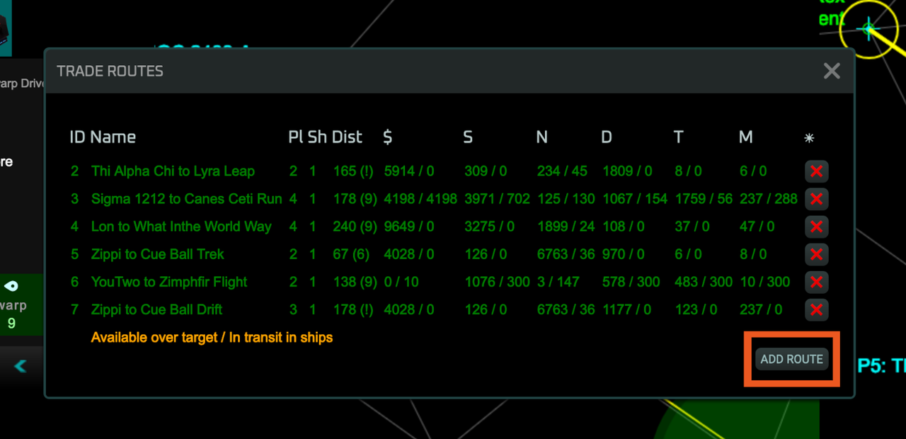
I've written a helper userscript for trade route management in VGA Planets NU.

For more information go here.

Trade Routes

Trade Routes Dialog

Blue Ruin

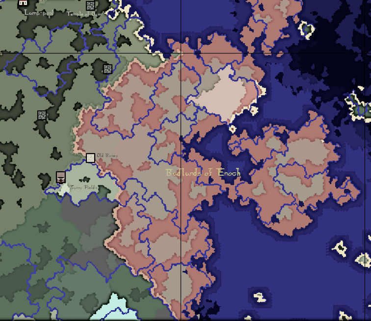
A new world for a new year.

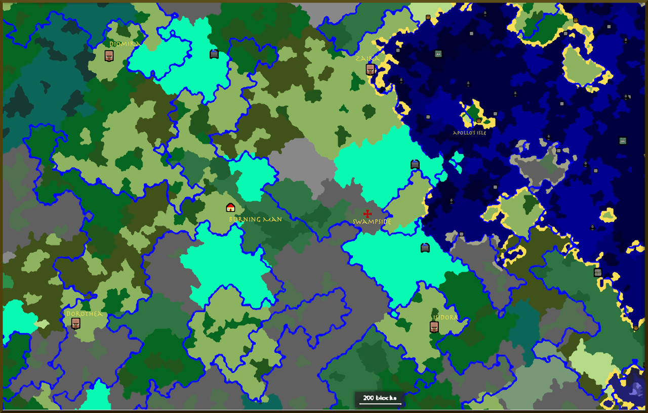
At the omphalos, fire and smoke rise from the Burning Man and candle towers light the way to the abandoned Ministry of Peace. Nearby at the base of the living tree dwelling of Swampside is the entrance to the rail system that links to the four cities at the corners of the known world, Diomira, a city of sixty silver domes, Isidora where the buildings have spiral staircases encrusted with spiral seashells, Dorothea with its four aluminium towers and women with fine teeth who look you straight in the eye, and not least, Zaira, the city of high bastions.

From their encampments and dark castles, seeking where to hide From the grim flames, and from the visions of Orc, in sight Of Albion’s Angel; who, enrag’d, his secret clouds open’d From North to South, and burnt outstretch’d on wings of wrath.

/images/minecraft/albions-map.png

Dark is the heaven above, and cold and hard the earth beneath: And, as a plague-wind, fill’d with insects, cuts off man and beast, And, as a sea o’erwhelms a land in the day of an earthquake, Fury, rage, madness, in a wind swept through Blue Ruin; And the red flames of Orc, that folded roaring, fierce, around The angry shores; and the fierce rushing of th’ inhabitants together! The citizens of Diomira close their books and lock their chests; The mariners of Zaira drop their anchors and unlade; The scribe of Dorothea casts his pen upon the earth; The builder of Isidora throws his hammer down in fear.

Lock Your Chests!

There is the odd light fingered player wandering about, who likes to peek into other people's chests and steal the interesting items.

Please don't do this!

However you can now protect your precious treasures by keeping them in a locked chest.

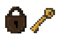
Lock and Key

/images/minecraft/lock-and-key.png

There are no actual locks or keys!

Instead you can use a Flint and Steel as a padlock. Simply give the Flint and Steel a secret name, using an Anvil, and you can use it to lock a chest.

You just have to use (right click on) the chest with the named Flint and Steel.

Now the chest will be locked so that it can only be opened when you are holding an item with the same name (a key).

For example, if you lock a chest using a Flint and Steel named, "My Precious", then you can unlock it with, say, a stick called "My Precious".

As an added bonus, the chest is unbreakable, and warded against thieves with a Fire Glyph.

You can unlock the chest by striking it (left click) with the key.

Doc Dragonbeard's Map

Forest Lodge Minecraft

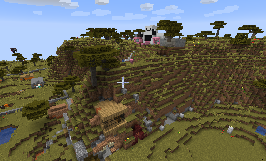
We run a friendly survival Minecraft server that you can join.

Some recent material has been found in a journal published by a probably self-educated "Doc" Dragonbeard.

Doc Dragonbeard's Map

His journal starts with the usual hopeful, "This is my new journal in which I will record all of my exciting adventures...", followed by blank page after blank page, with the occasional dated entry, along the lines of "Ate a pork chop this morning."

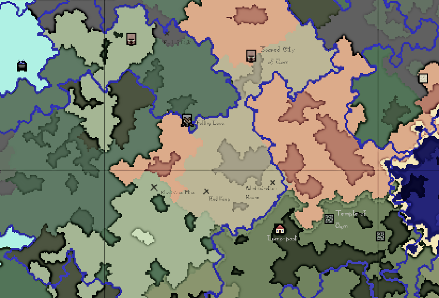
However there is one possibly valuable document, a map, over two pages:

/images/minecraft/doc-dragonbeard-1.png/images/minecraft/doc-dragonbeard-2.png

Play Minecraft With Rui

Forest Lodge Minecraft

We run a friendly survival Minecraft server that you can join. House rules are:

  • Be nice to each other, it's a cruel world full of brain eating zombies out there and you have to face it together

  • No name calling, no bad language

  • No stealing from other people's chests or destroying their houses

  • The server runs from mid-day to dusk on weekdays and from morning tea-time to bed time on weekends

Join Us

You will need to take the following steps to join.

/images/minecraft/mc-ss-0.png

Install Java Minecraft

The server is running Java Edition.

There are two editions of Minecraft. The original version, Java Edition, and Bedrock Edition. The Java version can run on Windows, Mac OS, Linux, Chromebooks. Bedrock runs on iPads, XBox, other consoles and on Windows.

I am biased, but the Bedrock Edition seems to be a "modern" game with lots of opportunities to buy upgrades and packs and tails and pets and cloaks. I don't trust it. The Java edition, on the other hand, is a nice old fashioned game; there is a one-time cost to buy an account, the game is in slow but constant development and there is a huge mod community of people running weird and wonderful servers.

Download The Game

You can download the game here.

/images/minecraft/mc-ss-2.png

Purchase An Account

You will need to purchase an account.

/images/minecraft/mc-ss-3.png

Run The Game

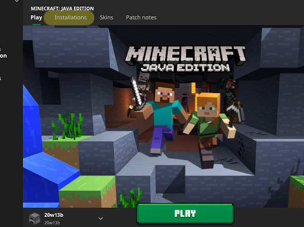
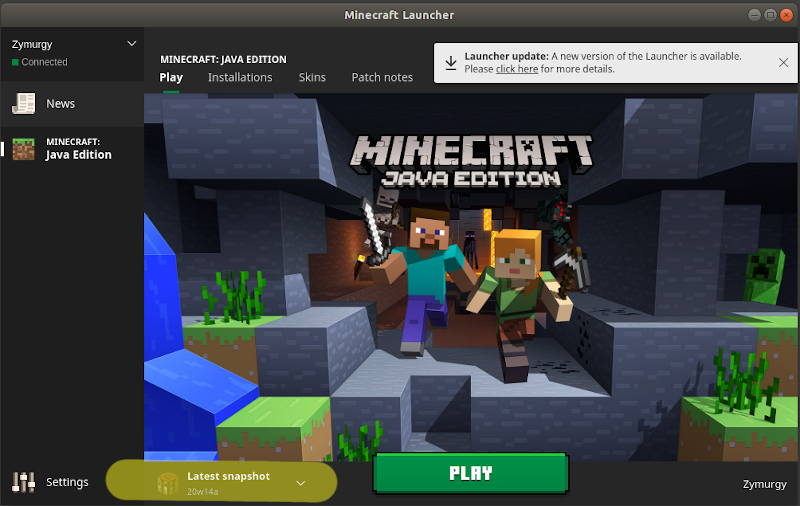
We try to keep the server on the latest snapshot. You can enable snapshots from the Minecraft Loader screen. Click the Installations menu at the top of the screen.

/images/minecraft/mc-ss-4.png

Use The Latest Snapshot

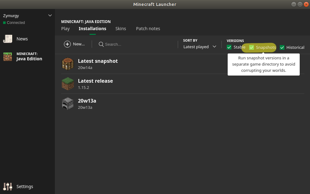
From the installations screen enable Snapshots, as in the screenshot below.

/images/minecraft/mc-ss-4-1.png

And then ensure that you have Latest Snapshot selected.

/images/minecraft/mc-ss-4-2.png

Connect To The Server

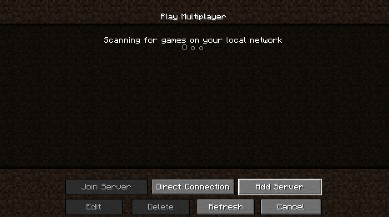
To add the server choose Multiplayer from the main screen and then choose Add Server.

/images/minecraft/mc-ss-7.png

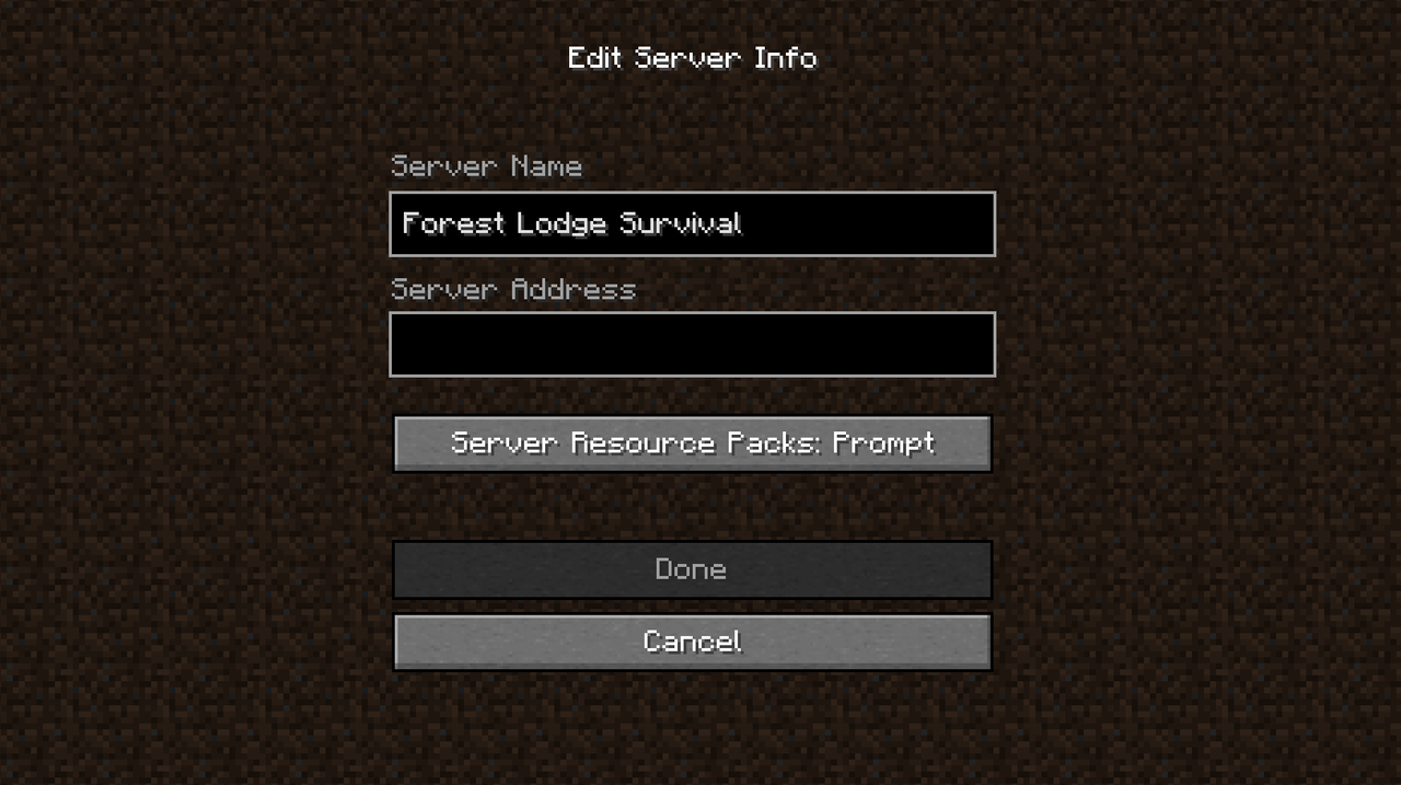
Enter a name of your choice for this server and the server address (which will be given to you separately).

/images/minecraft/mc-ss-8.png

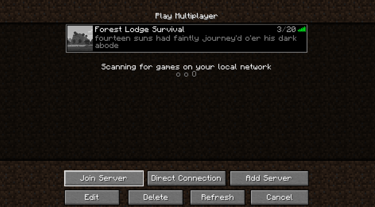
Then you should be able to join!

/images/minecraft/mc-ss-9.png

Arduino + Python + LED Matrix

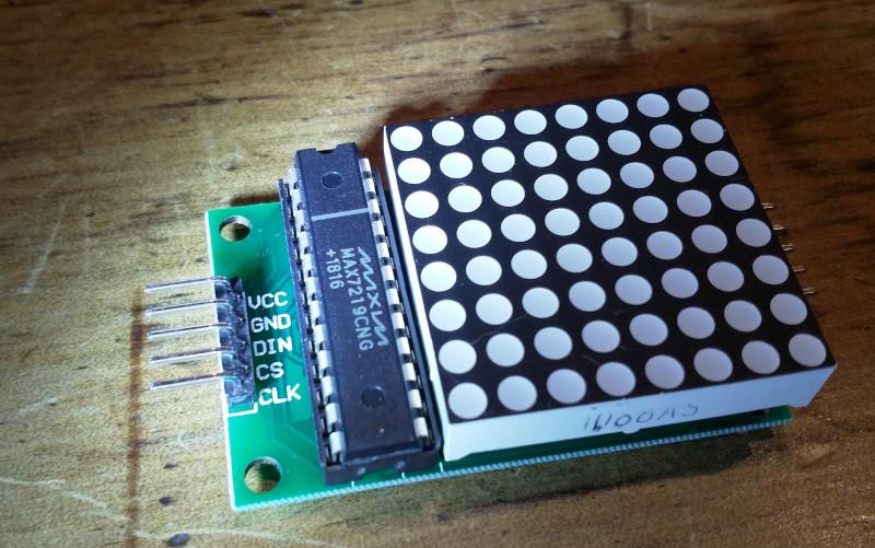
An LED Matrix

I went to Jaycar, looking for a WiFi module as I was thinking I'll need one for my e-paper calendar project. I walked out with a number of things including a Duinotech Uno with WiFi and an 8x8 red LED Matrix.

/images/arduino/led-1.jpg

OMG The Pins

This is a little lesson about reading the documentation. I spent hours trying to upload a blink sketch to the Uno. I tried all the boards available in the IDE. I loaded more boards using the IDE Boards Manager. I did rend my clothes and tear my hair. Finally I looked at the Jaycar site to try to find some howto stories.

On the product page linked above I found a note:

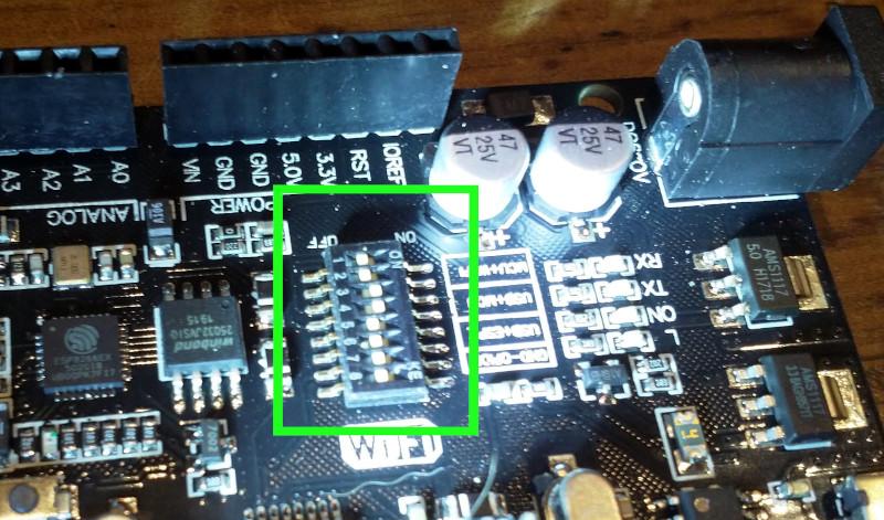
Please note: you must upload code to both processors then configure the switches for them to talk to each other

And a manual, and in the manual I found found some very clear instructions explaining that you have to set some dip switches on the board in order to program the Arduino MCU.

As they are two separate processors, you must upload code to both processors for them to function. You can set this by configuring the dip switches as per the table below, so that the USB/programmer can communicate between both processors individually. Once you have finished programming, configure the dip switches so both of the processors can communicate with each other to send messages back and forth.

/images/arduino/uno-dip-switches.jpg

For the moment I am not using the wireless functionality, so I've just set the dip switches so that I can program the Arduino MCU.

Interactivity

To work with the Arduino you have to be able to program it in C++. But the compile, upload, run loop of C++ can be daunting and time consuming. A more interactive programming cycle can give you more freedom to try out ideas, let you be more creative and is generally helpful for learning. I do a lot of programming in Python and I wanted to see if there was some practical way of working with the Arduino with Python.

Firmata

Firmata is a protocol for communicating with microcontrollers from software on a host computer. The protocol can be implemented in firmware on any microcontroller architecture as well as software on any host computer software package.

You load a general purpose sketch called StandardFirmata (or StandardFirmataPlus in this example) on the Arduino board and then use the host computer exclusively to interact with the Arduino board. In the Arduino IDE the Firmata sketches can be found in File -> Examples -> Firmata.

PyMata

PyMata is a Python library for interacting with an system running Firmata. The library has three flavours, the most straightforward of which lets you interact directly with the Arduino from the python interpreter.

Firmata Hello World

A basic Firmata hello world is to turn the on-board LED on and off.

First you load the Firmata sketch onto the Arduino. I tried StandardFirmataPlus. I quickly became apparent that this would not run on the Duemilanove. The only Firmata sketch the would was the OldStandardFirmata sketch. The python library, however, would not connect to this. In the end I got StandardFirmataPlus running with the Uno.

The python library was easy to install with pip install pymata-aio

Turning the on board LED on and off:

from pymata_aio.pymata3 import PyMata3
from pymata_aio.constants import Constants
board = PyMata3(arduino_wait=5)

BOARD_LED = 13
def setup():
    board.set_pin_mode(BOARD_LED, Constants.OUTPUT)

def loop():
    print("LED On")
    board.digital_write(BOARD_LED, 1)
    board.sleep(1.0)
    print("LED Off")
    board.digital_write(BOARD_LED, 0)
    board.sleep(1.0)

setup()
while True:
    loop()

MaxMatrix

But why just light up one LED when you can use 64? I did some work with the C++ MaxMatrix library and then ported it to python so I could drive the matrix from the python command line.

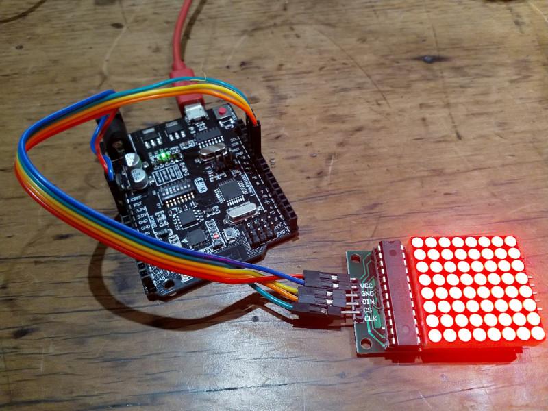
Wiring The LED

The LED is easy to wire. The VCC and GND pins should be connected to 5V and GND. The remaining pins can be connected to any digital pins on the board. They just have to be correctly identified when using the software.

/images/arduino/led-wiring.jpg

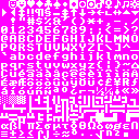
One nice thing about driving the Arduino interactively is that you don't need to worry about memory as much. I was able to add an additional method to the library to load a Dwarf Fortress tileset and use this as a convenient source of high quality 8x8-bit ascii graphics. I chose the Potash tileset

/images/Potash_8x8.png

Some sample code:

from pymata_aio.pymata3 import PyMata3
from pymata_aio.constants import Constants
import maxmatrix

board = PyMata3(arduino_wait=5)
# I wired the LED to 11, 12 and 13
DIN, CLK, CS = 12, 13, 11
mm = maxmatrix.MaxMatrix(board, DIN, CS, CLK)
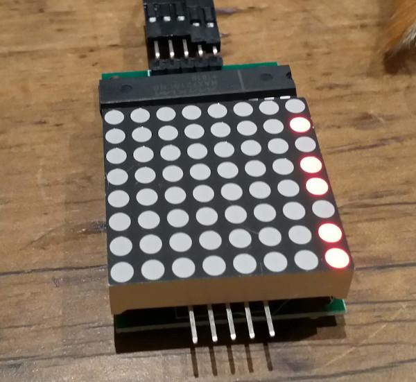
mm.set_column(0, 0b1011011)
/images/arduino/led-column.jpg

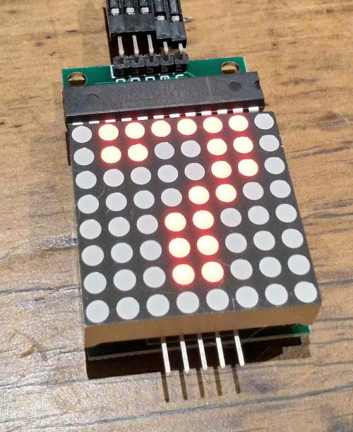
Working with sprites from a tileset:

ts = maxmatrix.Tileset()
sprite = ts.get_sprite('7')
mm.write_sprite(sprite)
/images/arduino/led-seven.jpg

maxmatrix.py

Full code listing of my python port of the MaxMatrix library.

maxmatrix.py (Source)

"""
A port of the MaxMatrix LED library to python for use with FirmataPlus.
"""
from pymata_aio.pymata3 import PyMata3        # type: ignore
from pymata_aio.constants import Constants    # type: ignore
from PIL import Image
MAX7219_REG_NOOP        = 0x00
MAX7219_REG_DIGIT0      = 0x01
MAX7219_REG_DIGIT1      = 0x02
MAX7219_REG_DIGIT2      = 0x03
MAX7219_REG_DIGIT3      = 0x04
MAX7219_REG_DIGIT4      = 0x05
MAX7219_REG_DIGIT5      = 0x06
MAX7219_REG_DIGIT6      = 0x07
MAX7219_REG_DIGIT7      = 0x08
MAX7219_REG_DECODEMODE  = 0x09
MAX7219_REG_INTENSITY   = 0x0a
MAX7219_REG_SCANLIMIT   = 0x0b
MAX7219_REG_SHUTDOWN    = 0x0c
MAX7219_REG_DISPLAYTEST = 0x0f
LOW, HIGH = 0, 1
LSBFIRST, MSBFIRST = 0, 1
# Following bit shifting functons adapted from https://wiki.python.org/moin/BitManipulation
def test_bit(value: int, offset: int) -> int:
    " Returns a 1, if the bit at 'offset' is one, else 0"
    mask = 1 << offset
    return 1 if (value & mask) else 0
def set_bit(value: int, offset: int) -> int:
    " Returns an integer with the bit at 'offset' set to 1"
    mask = 1 << offset
    return (value | mask)
def clear_bit(value: int, offset: int) -> int:
    " Returns an integer with the bit at 'offset' cleared "
    mask = ~(1 << offset)
    return (value & mask)
def toggle_bit(value: int, offset: int) -> int:
    " Returns an integer with the bit at 'offset' inverted, 0 -> 1 and 1 -> 0 "
    mask = 1 << offset
    return (value ^ mask)
def write_bit(value: int, offset: int, bit: int) -> int:
    if bit == HIGH:
        return set_bit(value, offset)
    elif bit == LOW:
        return clear_bit(value, offset)
    else:
        raise Exception("bit must be high or low")
class MaxMatrix:
    def __init__(self, board, data_pin: int, load_pin: int, clock_pin: int):
        self.board = board
        self.data_pin = data_pin
        self.load_pin = load_pin
        self.clock_pin = clock_pin
        self.buffer = bytearray(80)
        # initialise the LED display
        self.board.set_pin_mode(self.data_pin,  Constants.OUTPUT)
        self.board.set_pin_mode(self.clock_pin,  Constants.OUTPUT)
        self.board.set_pin_mode(self.load_pin,  Constants.OUTPUT)
        self.board.digital_write(self.clock_pin, HIGH)
        self.set_command(MAX7219_REG_SCANLIMIT, 0x07)
        self.set_command(MAX7219_REG_DECODEMODE, 0x00)   # using an led matrix (not digits)
        self.set_command(MAX7219_REG_SHUTDOWN, 0x01)     # not in shutdown mode
        self.set_command(MAX7219_REG_DISPLAYTEST, 0x00)  # no display test
        # empty registers, turn all LEDs off
        self.clear()
        self.set_intensity(0x0f)  # the first 0x0f is the value you can set
    def reload(self) -> None:
        for col in range(8):
            self.board.digital_write(self.load_pin, LOW)
            self.shift_out(col + 1)
            self.shift_out(self.buffer[col])
            self.board.digital_write(self.load_pin, LOW)
            self.board.digital_write(self.load_pin, HIGH)
    def clear(self):
        self.buffer = bytearray(80)
        self.reload()
    def set_command(self, command: int, value: int):
        self.board.digital_write(self.load_pin, LOW)
        self.shift_out(command)
        self.shift_out(value)
        self.board.digital_write(self.load_pin, LOW)
        self.board.digital_write(self.load_pin, HIGH)
    def shift_out(self, value: int, bit_order: int=MSBFIRST):
        # Adapted from hardware/arduino/avr/cores/arduino/wiring_shift.c
        for i in range(8):
            if bit_order == LSBFIRST:
                b = HIGH if ~~(value & (1 << i)) else LOW
            else:
                b = HIGH if ~~(value & (1 << (7 - i))) else LOW
            self.board.digital_write(self.data_pin, b)
            self.board.digital_write(self.clock_pin, HIGH)
            self.board.digital_write(self.clock_pin, LOW)
    def set_intensity(self, intensity: int):
        self.set_command(MAX7219_REG_INTENSITY, intensity)
    def set_column(self, col: int, value: int):
        """
        set the column to the value, for example:
        >>> mm.set_column(0, 0b11011001)
        """
        self.board.digital_write(self.load_pin, LOW)
        self.shift_out(col + 1)
        self.shift_out(value)
        self.board.digital_write(self.load_pin, LOW)
        self.board.digital_write(self.load_pin, HIGH)
        self.buffer[col] = value
    def set_row(self, row: int, value: int):
        """
        set the row to the value, for example:
        >>> mm.set_row(0, 0b11011001)
        """
        for i in range(8):
            b = test_bit(value, i)
            self.buffer[i] = write_bit(self.buffer[i], row, b)
        self.reload()
    def set_dot(self, col: int, row: int, value: int):
        self.buffer[col] = write_bit(self.buffer[col], row, value)
        self.board.digital_write(self.load_pin, LOW)
        self.shift_out(col + 1)
        self.shift_out(self.buffer[col])
        self.board.digital_write(self.load_pin, LOW)
        self.board.digital_write(self.load_pin, HIGH)
    def shift_left(self, fill_zero: bool = False):
        if fill_zero:
            self.buffer = self.buffer[-1:] + bytearray(1)
        else:
            self.buffer = self.buffer[-1:] + self.buffer[:-1]
        self.reload()
    def shift_right(self, fill_zero: bool = False):
        if fill_zero:
            self.buffer = self.buffer[1:] + bytearray(1)
        else:
            self.buffer = self.buffer[1:] + self.buffer[:1]
        self.reload()
    def shift_up(self, fill_zero: bool = False):
        for i in range(len(self.buffer)):
            if fill_zero:
                self.buffer[i] = self.buffer[i] << 1
            else:
                self.buffer[i] = ((self.buffer[i] << 1) & 0xff) | test_bit(self.buffer[i], 7)
        self.reload()
    def shift_down(self, fill_zero = False):
        for i in range(len(self.buffer)):
            if fill_zero:
                self.buffer[i] = self.buffer[i] >> 1
            else:
                self.buffer[i] = (self.buffer[i] >> 1) | (test_bit(self.buffer[i], 0) << 7)
        self.reload()
    def write_sprite(self, sprite: bytearray, x: int = 0, y: int = 0):
        if x:
            sprite = sprite[:]
            for i in range(8):
                sprite[i] = sprite[i] >> x
        self.buffer[y:y+8] = sprite
        self.reload()
def get_matrix(data, row, col):
    m = []
    for i in range(8):
        m.append(data[((i+8*col)*128) + (row * 8): ((i+8*col) * 128) + (row * 8) + 8])
    return m
def make_sprite(matrix):
    ba = bytearray(8)
    for r in range(8):
        for c in range(8):
            bit = matrix[r][c]
            ba[7 - c] = write_bit(ba[7 - c], 7 - r, bit)
    return ba
class Tileset:
    def __init__(self, tileset="Potash_8x8.png"):
        im = Image.open(tileset)
        data = list(im.getdata())
        sprites = {}
        for i in range(256):
            x, y = i % 16, i // 16
            m = get_matrix(data, x, y)
            sprites[i] = make_sprite(m)
        self.sprites = sprites
    def get_sprite(self, ch):
        return self.sprites[ord(ch)]

As I only have the one LED I haven't dealt with the parts of the MaxMatrix library that handle with multiple daisy-chained LEDs.

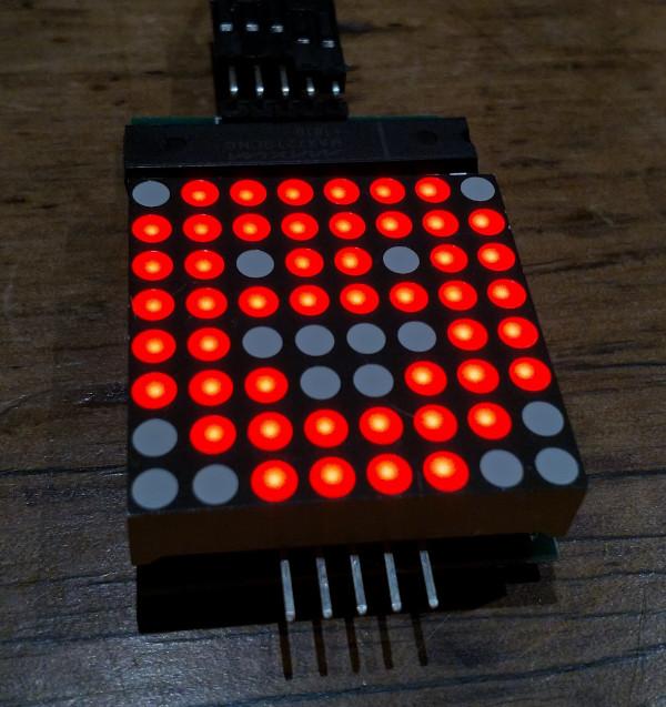
/images/arduino/led-happy.jpg

WaveShare E-Ink Display

E-Paper

I really like e-paper as a concept. Gentle on the eyes, holds an image with no power. So a long time ago I purchased a 4.3" WaveShare e-paper display and did nothing with it. It is quite a large display, 800x600 pixels and, despite the passage of many years since I bought it, still quite expensive at $121 from core-electronics.

/images/arduino/epaper-hello.jpg

Shown here with the pretty picture of a butterfly and a flower as it comes out of the box. Note also that I have it oriented in landscape with the wires on the left, more on this later.

I thought I'd try to put together a word-a-day e-paper calendar for the kitchen table, as I also like words.

First thing to do is to find some a sample word for which end I found Websters Unabridged Dictionary on Gutenberg.

Abhor

To shrink back with shuddering from; to regard with horror; to feel excessive repugnance toward; to detest; to loathe. Thou liest, abhorred tyrant; with my sword I'll prove the lie.

Connecting To The Arduino

The display has six wires. The documentation suggests that the blue (RST) wire does not need to be connected. In practice I found that it is better to not connect the white wire as well.

If the white wire is connected then it is not possible to upload a sketch as an error occurs:

avrdude: stk500_getsync() attempt 1 of 10: not in sync: resp=0xa5

The documentation suggests that you disconnect the green and white wires (RX and TX) while uploading a sketch. The you have to press the reset button to start the sketch again. If instead you just don't connect the white (RX) wire at all, everything works fine.

Wiring

Arduino

4.3" e-Paper

5v

Red

GND

Black

RX/D0

White*

TX/D1

Green

D2

Yellow

RST

Blue*

  • Don't connect the blue or white wires

E-Paper Hello World

Following is a basic hello world program that displays the butterfly and flower image that is in the internal memory.

epaper_hello.ino (Source)

#include <epd.h>
const int led = 13;
void setup() {
  /*
  user led init
  */
  pinMode(led, OUTPUT);
  digitalWrite(led, LOW);
  epd_init();
  epd_wakeup();
  epd_set_memory(MEM_NAND);
  epd_screen_rotation(EPD_INVERSION);
}
void loop() {
  // put your main code here, to run repeatedly:
  epd_clear();
  epd_disp_bitmap("PIC7.BMP", 0, 0);
  epd_udpate();
  epd_enter_stopmode();
  char flag = 0;
  while (1)
  {
    if(flag)
    {
      flag = 0;
      digitalWrite(led, LOW);
      delay(1000);
    }
    else
    {
      flag = 1;
      digitalWrite(led, HIGH);
      delay(3000);
    }
  }
}

Things to note:

  • line 13: epd_wakeup because we put it to sleep earlier. While it is awake it draws a fair amount of power.

  • line 15: set the screen orientation to landscape, with wires on the left

  • lines 21-23: clear the display, load a picture from the internal flash memory and update the display

  • line 25: epd_enter_stopmode so it stops drawing power. Note the red light at the top left turns off.

Then the on-board LED starts flashing again. Just so it is clear that there is something happening.

E-Paper Calendar

My vision of an epaper word-a-day calendar is a little more challenging than I had at first anticipated. The software for drawing to the display is extremely rudimentary, with commands to display text, an image from the SD card or internal NAND flash and basic vector drawing commands.

void epd_draw_pixel(int x0, int y0);
void epd_draw_line(int x0, int y0, int x1, int y1);
void epd_fill_rect(int x0, int y0, int x1, int y1);
void epd_draw_circle(int x0, int y0, int r);
void epd_fill_circle(int x0, int y0, int r);
void epd_draw_triangle(int x0, int y0, int x1, int y1, int x2, int y2);
void epd_fill_triangle(int x0, int y0, int x1, int y1, int x2, int y2);
void epd_clear(void);

void epd_disp_char(unsigned char ch, int x0, int y0);
void epd_disp_string(const void * p, int x0, int y0);

void epd_disp_bitmap(const void * p, int x0, int y0);

There is also an exciting looking function for writing images to the SD card documented in the manual, but there are no library functions to use this functionality.

Send a file to the SD card using UART (0x40) After this command executed, any data from UART will be saved into the SD card and saved with the given filename. If the transmission stops more than 1s, this function will stop too. After the file sent, file size and Xor check will be returned and you should compare them to check if the file was sent properly. Last, if the file was sent properly, you should send the character ‘y’ to confirm. If the file is an image (.JPG or .BMP), you should set the storage area to SD card (A5 00 0A 07 01 CC 33 C3 3C A9), and then use the display image command to display it. UART input stream command is not affected by the storage area settings.Files are only going to be saved into the Micro SD card.

Nevertheless I laboriously laid out a basic mockup of a calendar page. While laying this out I used a grid of points to help align the text.

/**
* Draw a grid from (t,l) with points spaced `w` pixels apart and with
* major `tick` marks as specified.
*/
void draw_grid(int t, int l, int w, int tick) {
  int i = 0;
  int j = 0;
  for (int x = l; x <= 800; x += w) {
    i++;
    for (int y = t; y <= 600; y += w) {
      j++;
      epd_draw_pixel(x, y);
      if ((i % tick == 0) && (j % tick == 0)) {
        draw_tick(x, y);
      }
    }
  }
}

The finished sample:

/images/arduino/epaper-calendar.jpg

The code:

epaper_calendar.ino (Source)

#include <epd.h>
const int led = 13;
void setup() {
  /*
  user led init
  */
  pinMode(led, OUTPUT);
  digitalWrite(led, LOW);
  // random number seeding
  Serial.begin(9600);
  // if analog input pin 0 is unconnected, random analog
  // noise will cause the call to randomSeed() to generate
  // different seed numbers each time the sketch runs.
  randomSeed(analogRead(0));
  epd_init();
  epd_wakeup();
  epd_set_memory(MEM_NAND);
  epd_screen_rotation(EPD_INVERSION);
}
void loop() {
  char flag = 0;
  draw_calendar();
  epd_enter_stopmode();
  while (1)
  {
    if(flag)
    {
      flag = 0;
      digitalWrite(led, LOW);
      delay(1000);
    }
    else
    {
      flag = 1;
      digitalWrite(led, HIGH);
      delay(3000);
    }
  }
}
void draw_calendar(void) {
  char const *date[] = {"Saturday", "04", "January", "2020"};
  char const *title = " ABHOR-";
  char const *words[] = {
    "To shrink back with shuddering from; to",
    "regard with horror; to feel excessive",
    "repugnance toward; to detest; to loathe.",
    "  Thou liest, abhorred tyrant; with my ",
    "sword I'll prove the lie."
  };
  epd_clear();
  // draw the word of the day
  epd_set_color(BLACK, WHITE);
  epd_set_en_font(ASCII48);
  epd_disp_string(title, 8, 8);
  // draw the definition
  epd_set_en_font(ASCII32);
  epd_set_color(DARK_GRAY, WHITE);
  for (int i=0; i<5; i++) {
    epd_disp_string(words[i], 16, 58 + (38 * i));
  }
  // draw the date
  epd_set_color(DARK_GRAY, WHITE);
  epd_set_en_font(ASCII48);
  epd_disp_string(date[0], 578, 13);
  epd_set_color(BLACK, WHITE);
  epd_set_en_font(ASCII64);
  epd_disp_string(date[1], 633, 59);
  epd_set_color(DARK_GRAY, WHITE);
  epd_set_en_font(ASCII48);
  epd_disp_string(date[2], 578, 117);
  epd_set_color(BLACK, WHITE);
  epd_disp_string(date[3], 616, 169);
  // draw a decorative border around the screen
  for (int i=0; i < 4; i++) {
    epd_set_color(DARK_GRAY, WHITE);
    draw_rect(i, i, 799 - (2*i), 599 - (2*i));
  }
  // draw a light gray round ended line between the date and the word of the day
  for (int i=0; i < 5; i++) {
    int h = abs(i-2) * 2;
    epd_set_color(GRAY, WHITE);
    epd_draw_line(540 + i, 18 + h, 540 + i, 578 - h);
  }
  // draw_grid(8, 8, 10, 5);
  epd_udpate();
}
void draw_rect(int t, int l, int h, int w) {
  epd_draw_line(t, l, t, l + w);
  epd_draw_line(t, l, t + h, l);
  epd_draw_line(t + h, l, t + h, l + w);
  epd_draw_line(t, l + w, t + h, l + w);
}
/**
* Draw a grid from (t,l) with points spaced `w` pixels apart and with
* major `tick` marks as specified.
*/
void draw_grid(int t, int l, int w, int tick) {
  int i = 0;
  int j = 0;
  for (int x = l; x <= 800; x += w) {
    i++;
    for (int y = t; y <= 600; y += w) {
      j++;
      epd_draw_pixel(x, y);
      if ((i % tick == 0) && (j % tick == 0)) {
        draw_tick(x, y);
      }
    }
  }
}
/**
* Draw a major tick mark at the point specified.
*/
void draw_tick(int x, int y) {
  epd_draw_pixel(x - 1, y);
  epd_draw_pixel(x + 1, y);
  epd_draw_pixel(x, y - 1);
  epd_draw_pixel(x, y + 1);
}

Clearly this project needs a higher level text layout capability. An interesting solution to this problem is to build an image on a remote server and then chop it into scanlines which are then delivered piecemeal over wifi.

Resources

Getting Started With Arduino

Arduino Programming

I have an old Arduino Duemilanove board that I bought a long time ago and have since neglected.

This is a very old board, first released in 2009 and no longer available except maybe on Ebay.

/images/arduino/arduino-duemilanove.jpg

To get started with using this microcontroller you have to download the Arduino IDE.

Arduino IDE

Download the Arduino IDE and install. It is likely that you will have to add your user account to the dialout group and log in again. I also had to make the /dev/ttyUSB0 device group read+write-able. There may be other ways to do this but I used reliable old chmod g+rw /dev/ttyUSB0.

A good hello world project is to upload the blink sketch. This makes the onboard LED flash, which confirms that you are able to do something with the microcontroller.

I modified the sketch slightly to make the LED stay on for three seconds, just to be sure .

/*
  Blink

  Turns an LED on for three seconds, then off for one second, repeatedly.

  http://www.arduino.cc/en/Tutorial/Blink
*/

// the setup function runs once when you press reset or power the board
void setup() {
  // initialize digital pin LED_BUILTIN as an output.
  pinMode(LED_BUILTIN, OUTPUT);
}

// the loop function runs over and over again forever
void loop() {
  digitalWrite(LED_BUILTIN, HIGH);   // turn the LED on (HIGH is the voltage level)
  delay(3000);                       // wait for a second
  digitalWrite(LED_BUILTIN, LOW);    // turn the LED off by making the voltage LOW
  delay(1000);                       // wait for a second
}

Click the Verify (tick mark) and Upload (right arrow) buttons and the sketch should upload to the board and the LED should start blinking.

/images/arduino/arduino-ide-closeup.png

Trouble

I had a lot of trouble getting this to work at all. There are a lot of basic things that you have to get right.

  • As mentioned, fix group access permissions to the USB device.

  • Make sure you have selected the right board from the Tools > Board menu, it won't be auto-detected for you.

/images/arduino/arduino-ide.png
  • Select the right processor from the Tools > Processor menu. It might help to have a close look at the chip on the board to work out which one it is.

/images/arduino/arduino-duemilanove-closeup.jpg
  • If this all fails, you can turn on additional debugging output from File > Preferences > Show Verbose Output and start searching Stack Overflow.