Arduino + Python + LED Matrix

An LED Matrix

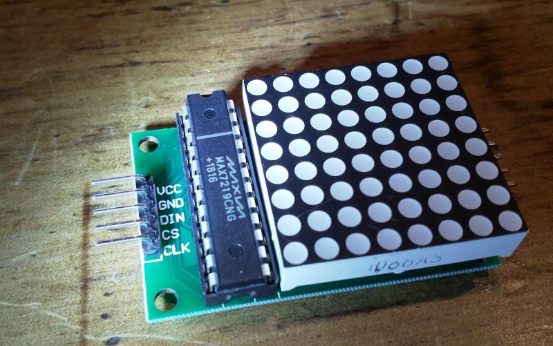
I went to Jaycar, looking for a WiFi module as I was thinking I'll need one for my e-paper calendar project. I walked out with a number of things including a Duinotech Uno with WiFi and an 8x8 red LED Matrix.
/images/arduino/led-1.jpg

OMG The Pins

This is a little lesson about reading the documentation. I spent hours trying to upload a blink sketch to the Uno. I tried all the boards available in the IDE. I loaded more boards using the IDE Boards Manager. I did rend my clothes and tear my hair. Finally I looked at the Jaycar site to try to find some howto stories.

On the product page linked above I found a note:

Please note: you must upload code to both processors then configure the switches for them to talk to each other

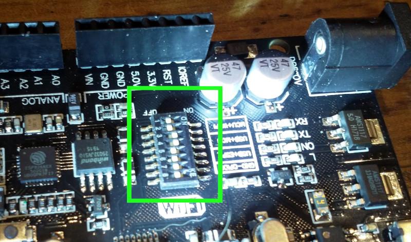
And a manual, and in the manual I found found some very clear instructions explaining that you have to set some dip switches on the board in order to program the Arduino MCU.

As they are two separate processors, you must upload code to both processors for them to function. You can set this by configuring the dip switches as per the table below, so that the USB/programmer can communicate between both processors individually. Once you have finished programming, configure the dip switches so both of the processors can communicate with each other to send messages back and forth.
/images/arduino/uno-dip-switches.jpg

For the moment I am not using the wireless functionality, so I've just set the dip switches so that I can program the Arduino MCU.

Interactivity

To work with the Arduino you have to be able to program it in C++. But the compile, upload, run loop of C++ can be daunting and time consuming. A more interactive programming cycle can give you more freedom to try out ideas, let you be more creative and is generally helpful for learning. I do a lot of programming in Python and I wanted to see if there was some practical way of working with the Arduino with Python.

Firmata

Firmata is a protocol for communicating with microcontrollers from software on a host computer. The protocol can be implemented in firmware on any microcontroller architecture as well as software on any host computer software package.

You load a general purpose sketch called StandardFirmata (or StandardFirmataPlus in this example) on the Arduino board and then use the host computer exclusively to interact with the Arduino board. In the Arduino IDE the Firmata sketches can be found in File -> Examples -> Firmata.

PyMata

PyMata is a Python library for interacting with an system running Firmata. The library has three flavours, the most straightforward of which lets you interact directly with the Arduino from the python interpreter.

Firmata Hello World

A basic Firmata hello world is to turn the on-board LED on and off.

First you load the Firmata sketch onto the Arduino. I tried StandardFirmataPlus. I quickly became apparent that this would not run on the Duemilanove. The only Firmata sketch the would was the OldStandardFirmata sketch. The python library, however, would not connect to this. In the end I got StandardFirmataPlus running with the Uno.

The python library was easy to install with pip install pymata-aio

Turning the on board LED on and off:

from pymata_aio.pymata3 import PyMata3
from pymata_aio.constants import Constants
board = PyMata3(arduino_wait=5)

BOARD_LED = 13
def setup():
    board.set_pin_mode(BOARD_LED, Constants.OUTPUT)

def loop():
    print("LED On")
    board.digital_write(BOARD_LED, 1)
    board.sleep(1.0)
    print("LED Off")
    board.digital_write(BOARD_LED, 0)
    board.sleep(1.0)

setup()
while True:
    loop()

MaxMatrix

But why just light up one LED when you can use 64? I did some work with the C++ MaxMatrix library and then ported it to python so I could drive the matrix from the python command line.

Wiring The LED

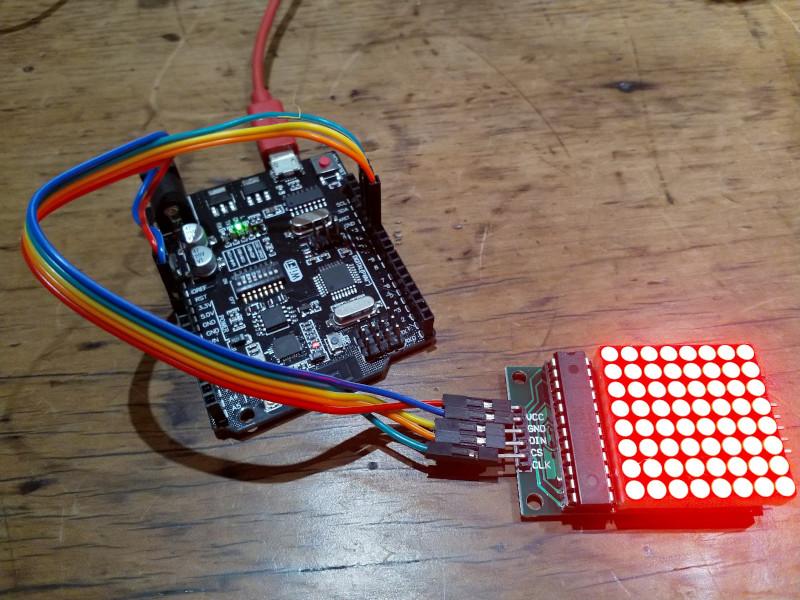
The LED is easy to wire. The VCC and GND pins should be connected to 5V and GND. The remaining pins can be connected to any digital pins on the board. They just have to be correctly identified when using the software.
/images/arduino/led-wiring.jpg

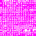
One nice thing about driving the Arduino interactively is that you don't need to worry about memory as much. I was able to add an additional method to the library to load a Dwarf Fortress tileset and use this as a convenient source of high quality 8x8-bit ascii graphics. I chose the Potash tileset
/images/Potash_8x8.png

Some sample code:

from pymata_aio.pymata3 import PyMata3
from pymata_aio.constants import Constants
import maxmatrix

board = PyMata3(arduino_wait=5)
# I wired the LED to 11, 12 and 13
DIN, CLK, CS = 12, 13, 11
mm = maxmatrix.MaxMatrix(board, DIN, CS, CLK)
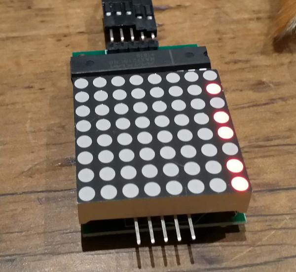
mm.set_column(0, 0b1011011)
/images/arduino/led-column.jpg

Working with sprites from a tileset:

ts = maxmatrix.Tileset()
sprite = ts.get_sprite('7')
mm.write_sprite(sprite)
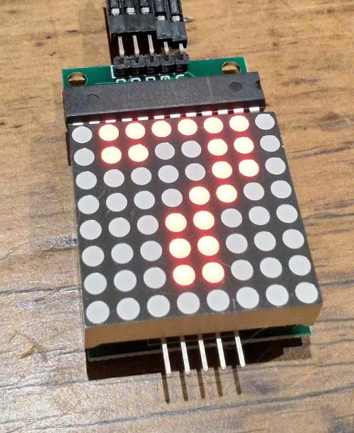
/images/arduino/led-seven.jpg

maxmatrix.py

Full code listing of my python port of the MaxMatrix library.

maxmatrix.py (Source)

"""
A port of the MaxMatrix LED library to python for use with FirmataPlus.
"""
from pymata_aio.pymata3 import PyMata3        # type: ignore
from pymata_aio.constants import Constants    # type: ignore
from PIL import Image
MAX7219_REG_NOOP        = 0x00
MAX7219_REG_DIGIT0      = 0x01
MAX7219_REG_DIGIT1      = 0x02
MAX7219_REG_DIGIT2      = 0x03
MAX7219_REG_DIGIT3      = 0x04
MAX7219_REG_DIGIT4      = 0x05
MAX7219_REG_DIGIT5      = 0x06
MAX7219_REG_DIGIT6      = 0x07
MAX7219_REG_DIGIT7      = 0x08
MAX7219_REG_DECODEMODE  = 0x09
MAX7219_REG_INTENSITY   = 0x0a
MAX7219_REG_SCANLIMIT   = 0x0b
MAX7219_REG_SHUTDOWN    = 0x0c
MAX7219_REG_DISPLAYTEST = 0x0f
LOW, HIGH = 0, 1
LSBFIRST, MSBFIRST = 0, 1
# Following bit shifting functons adapted from https://wiki.python.org/moin/BitManipulation
def test_bit(value: int, offset: int) -> int:
    " Returns a 1, if the bit at 'offset' is one, else 0"
    mask = 1 << offset
    return 1 if (value & mask) else 0
def set_bit(value: int, offset: int) -> int:
    " Returns an integer with the bit at 'offset' set to 1"
    mask = 1 << offset
    return (value | mask)
def clear_bit(value: int, offset: int) -> int:
    " Returns an integer with the bit at 'offset' cleared "
    mask = ~(1 << offset)
    return (value & mask)
def toggle_bit(value: int, offset: int) -> int:
    " Returns an integer with the bit at 'offset' inverted, 0 -> 1 and 1 -> 0 "
    mask = 1 << offset
    return (value ^ mask)
def write_bit(value: int, offset: int, bit: int) -> int:
    if bit == HIGH:
        return set_bit(value, offset)
    elif bit == LOW:
        return clear_bit(value, offset)
    else:
        raise Exception("bit must be high or low")
class MaxMatrix:
    def __init__(self, board, data_pin: int, load_pin: int, clock_pin: int):
        self.board = board
        self.data_pin = data_pin
        self.load_pin = load_pin
        self.clock_pin = clock_pin
        self.buffer = bytearray(80)
        # initialise the LED display
        self.board.set_pin_mode(self.data_pin,  Constants.OUTPUT)
        self.board.set_pin_mode(self.clock_pin,  Constants.OUTPUT)
        self.board.set_pin_mode(self.load_pin,  Constants.OUTPUT)
        self.board.digital_write(self.clock_pin, HIGH)
        self.set_command(MAX7219_REG_SCANLIMIT, 0x07)
        self.set_command(MAX7219_REG_DECODEMODE, 0x00)   # using an led matrix (not digits)
        self.set_command(MAX7219_REG_SHUTDOWN, 0x01)     # not in shutdown mode
        self.set_command(MAX7219_REG_DISPLAYTEST, 0x00)  # no display test
        # empty registers, turn all LEDs off
        self.clear()
        self.set_intensity(0x0f)  # the first 0x0f is the value you can set
    def reload(self) -> None:
        for col in range(8):
            self.board.digital_write(self.load_pin, LOW)
            self.shift_out(col + 1)
            self.shift_out(self.buffer[col])
            self.board.digital_write(self.load_pin, LOW)
            self.board.digital_write(self.load_pin, HIGH)
    def clear(self):
        self.buffer = bytearray(80)
        self.reload()
    def set_command(self, command: int, value: int):
        self.board.digital_write(self.load_pin, LOW)
        self.shift_out(command)
        self.shift_out(value)
        self.board.digital_write(self.load_pin, LOW)
        self.board.digital_write(self.load_pin, HIGH)
    def shift_out(self, value: int, bit_order: int=MSBFIRST):
        # Adapted from hardware/arduino/avr/cores/arduino/wiring_shift.c
        for i in range(8):
            if bit_order == LSBFIRST:
                b = HIGH if ~~(value & (1 << i)) else LOW
            else:
                b = HIGH if ~~(value & (1 << (7 - i))) else LOW
            self.board.digital_write(self.data_pin, b)
            self.board.digital_write(self.clock_pin, HIGH)
            self.board.digital_write(self.clock_pin, LOW)
    def set_intensity(self, intensity: int):
        self.set_command(MAX7219_REG_INTENSITY, intensity)
    def set_column(self, col: int, value: int):
        """
        set the column to the value, for example:
        >>> mm.set_column(0, 0b11011001)
        """
        self.board.digital_write(self.load_pin, LOW)
        self.shift_out(col + 1)
        self.shift_out(value)
        self.board.digital_write(self.load_pin, LOW)
        self.board.digital_write(self.load_pin, HIGH)
        self.buffer[col] = value
    def set_row(self, row: int, value: int):
        """
        set the row to the value, for example:
        >>> mm.set_row(0, 0b11011001)
        """
        for i in range(8):
            b = test_bit(value, i)
            self.buffer[i] = write_bit(self.buffer[i], row, b)
        self.reload()
    def set_dot(self, col: int, row: int, value: int):
        self.buffer[col] = write_bit(self.buffer[col], row, value)
        self.board.digital_write(self.load_pin, LOW)
        self.shift_out(col + 1)
        self.shift_out(self.buffer[col])
        self.board.digital_write(self.load_pin, LOW)
        self.board.digital_write(self.load_pin, HIGH)
    def shift_left(self, fill_zero: bool = False):
        if fill_zero:
            self.buffer = self.buffer[-1:] + bytearray(1)
        else:
            self.buffer = self.buffer[-1:] + self.buffer[:-1]
        self.reload()
    def shift_right(self, fill_zero: bool = False):
        if fill_zero:
            self.buffer = self.buffer[1:] + bytearray(1)
        else:
            self.buffer = self.buffer[1:] + self.buffer[:1]
        self.reload()
    def shift_up(self, fill_zero: bool = False):
        for i in range(len(self.buffer)):
            if fill_zero:
                self.buffer[i] = self.buffer[i] << 1
            else:
                self.buffer[i] = ((self.buffer[i] << 1) & 0xff) | test_bit(self.buffer[i], 7)
        self.reload()
    def shift_down(self, fill_zero = False):
        for i in range(len(self.buffer)):
            if fill_zero:
                self.buffer[i] = self.buffer[i] >> 1
            else:
                self.buffer[i] = (self.buffer[i] >> 1) | (test_bit(self.buffer[i], 0) << 7)
        self.reload()
    def write_sprite(self, sprite: bytearray, x: int = 0, y: int = 0):
        if x:
            sprite = sprite[:]
            for i in range(8):
                sprite[i] = sprite[i] >> x
        self.buffer[y:y+8] = sprite
        self.reload()
def get_matrix(data, row, col):
    m = []
    for i in range(8):
        m.append(data[((i+8*col)*128) + (row * 8): ((i+8*col) * 128) + (row * 8) + 8])
    return m
def make_sprite(matrix):
    ba = bytearray(8)
    for r in range(8):
        for c in range(8):
            bit = matrix[r][c]
            ba[7 - c] = write_bit(ba[7 - c], 7 - r, bit)
    return ba
class Tileset:
    def __init__(self, tileset="Potash_8x8.png"):
        im = Image.open(tileset)
        data = list(im.getdata())
        sprites = {}
        for i in range(256):
            x, y = i % 16, i // 16
            m = get_matrix(data, x, y)
            sprites[i] = make_sprite(m)
        self.sprites = sprites
    def get_sprite(self, ch):
        return self.sprites[ord(ch)]

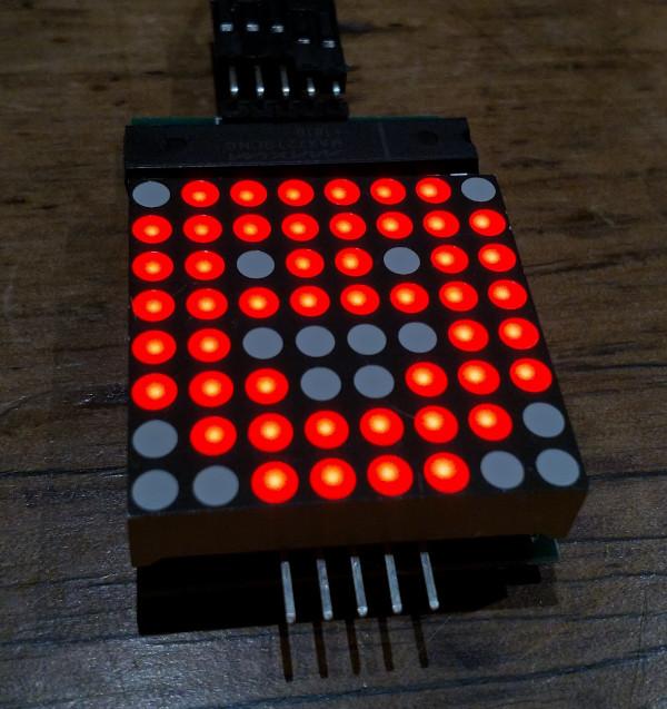
As I only have the one LED I haven't dealt with the parts of the MaxMatrix library that handle with multiple daisy-chained LEDs.
/images/arduino/led-happy.jpg

Comments

Comments powered by Disqus